With this post I wanted to discuss how association and authentication looks like with 802.11ah. Below is the overview of how a S1G STA is connecting to an S1G AP on frame level, as you notice this is a WPA2-PSK authentication and it looks very similar to a an authentication in 2.4 or 5GHz.
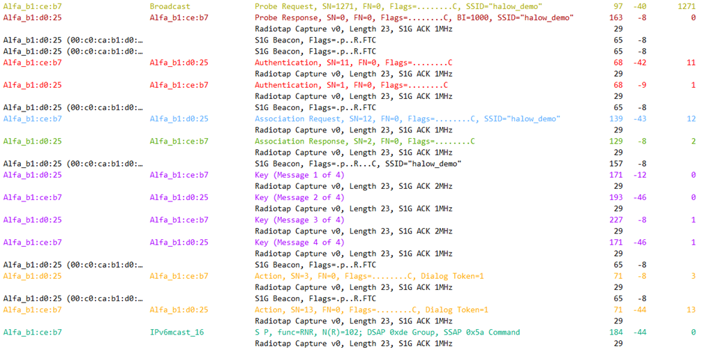
To complete a full network authentication we need to go through the 4 steps of the 802.11 State machine
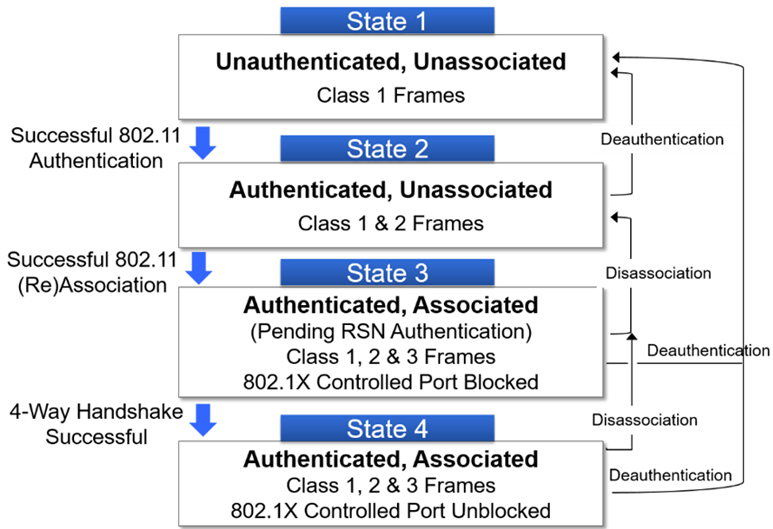
STATE 1 : Discovery
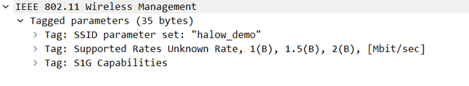
First thing a STA should do is perform discovery on the network, in the STA the SSID to connect with was configured. The STA sent out a Probe Request from for the SSID halow_demo, the Probe Request is providing the SSID Parameter set, the supported data rates and the S1G capabilities of the STA. The Probe Request has a length of 97 bytes
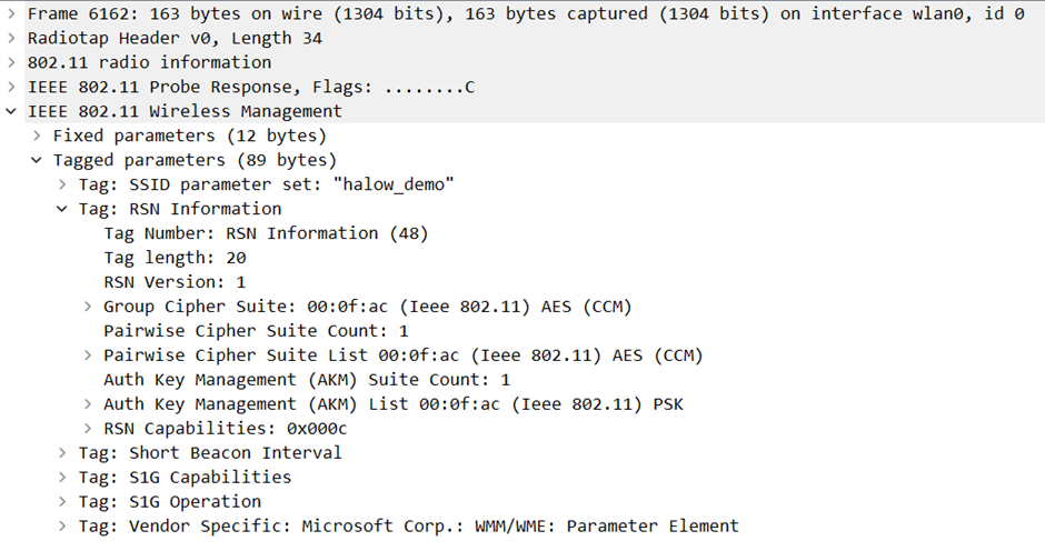
The S1G access point will reply with a Probe Response and presenting its S1G capabilities to the STA. Just as frames on 2.4 and 5Ghz the Probe Response frames look very similar to Beacon frames that we discussed in an earlier blogpost. In this capture we found the RSN Information Element showing the encryption method for Unicast, multicast/broadcast traffic and also the authentication method. In our case we use WPA2-PSK authentication with AES encryption.
Because the Probe Response is a Unicast frame it needs to be acknowledged, as an ACK to the Probe Response we find an S1G NDP CMAC frame . Different types of NDP CMAC PPDY exist and they have the same rules as with similar MPDUs
| Value | Meaning |
| 0 | NDP CTS or NDP CF-End |
| 1 | NDP PS-Poll |
| 2 | NDP Ack |
| 3 | NDP PS-Poll-Ack |
| 4 | NDP BlockAck |
| 5 | NDP Beamforming Report Poll |
| 6 | NDP Paging |
| 7 | NDP Probe Request |
The frame format for the S1G NDP CMAC frame for 1MHz looks like this
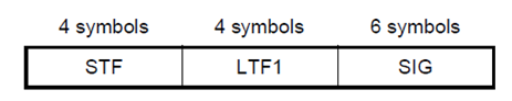
- Short Training Field has 4 symbols
- Long Training Field has 4 symbols
- SIG field is made of 6 symbols and the format for the SIG field format for 1MHz will look like figure 6
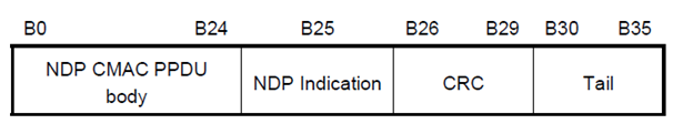
- NDP CMAC PPDU body field will be explained below
- NDP Indication field is set to 1 to indicate this is a NDP CMAC PPDU
- CRC Field is described in 23.3.8.2.2.6
- Tail field is set to 0
The NDP CMAC PPDY body can again be sub-divided in several fields, below is the format for the NDP CMAC PPDU body field of the NDP_1M Ack frame. The NDP CMAC PPDU body field has 25 bits
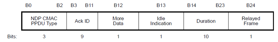
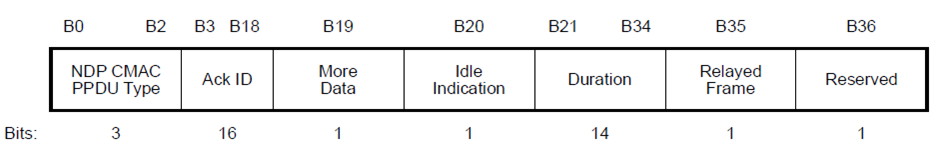
- NDP CMAC PPDU type field is set to 2 because this is an ACK frame
- ACK Id is set to the bit sequence Scrambler Initialization, this Scrambler Initialization value is found in the RXVECTOR parameter SCRAMBLER_OR_CRC
- More Data field is used different for S1G compared to other PHYs.
An S1G station will set the More Data field to 1 if it has MSDU, MMPDU or A-MSDU buffered for transmission during the current TXOP. An S1G AP will set the More Data field to 1 in group addressed frames if additional group addressed BU need to be transmitted by the AP in the beacon interval or short beacon interval.
- Idle Indication field is 0 , the Duration field is retrieved from the Duration/ID field of the frame that initiated the response minus the time, in µs, between the end of the PPDU and the end of the NDP Ack frame. Exception on this is when the frame that initiated the NDP Ack is a PS-Poll frame
When the Idle Indication field is 1 then the Duration field is set to the duration in milliseconds for the idle period we expect from the station that initiated the response. The duration is started from the end of the NDP Ack frame response.
Note : the metric for the Duration field is different depending on the value in the Idle Indication field, microseconds if Idle Indication is 0 and milliseconds if Idle Indication is 1
- The Relayed Frame field can be set to 0 or 1 when doing TXOP sharing.
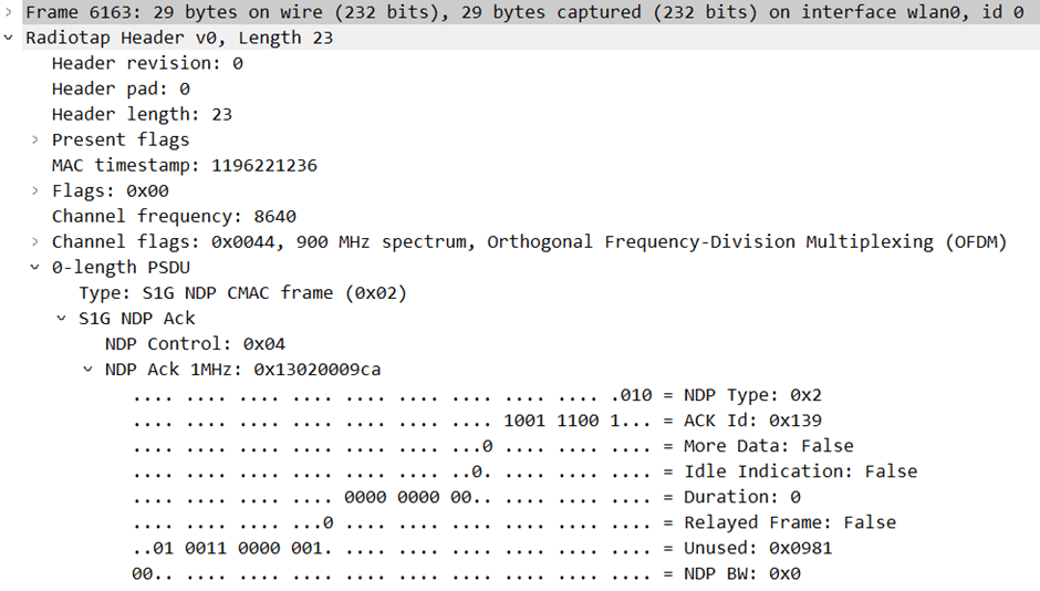
In wireshark you can find this as the frame below, notice this is for 1MHz frames.
An S1G NDP CMAC PPDU for 2MHz, 4MHz, 8MHz or 16MHz will have a format that looks like below
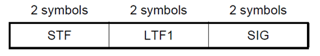
- Short Training Field has 2 symbols
- Long Training Field has 2 symbols
- SIG field is made of 2 symbols and the format for the SIG field format for 2MHz will look like figure 10
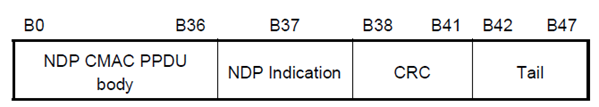
The NDP CMAC PPDU body for 2MHz and larger can be split into separate fields again, just like with 1MHz but now the NDP CMAC PPDU body exists of 37 bits instead of 25.
You will see the same fields in an NDP Ack frame for 1 MHz as in an NDP Ack for 2MHz, only the number of bits for Ack ID and duration changed.
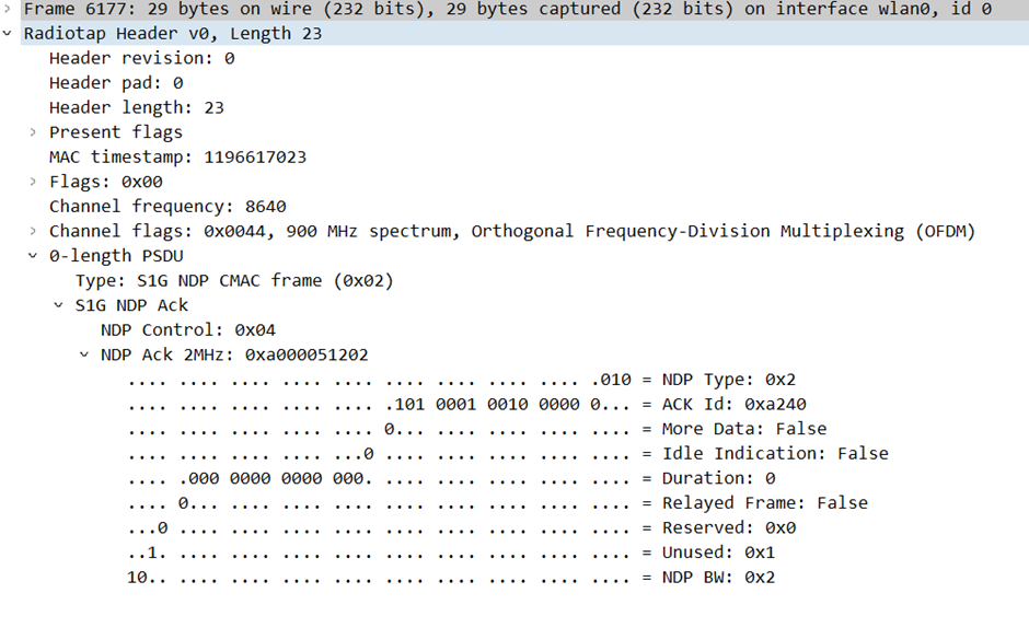
Back to our authentication, with the S1G ACK 1MHz frame we have acknowledged the Probe Response.
STATE 2 : Authenticated and Unassociated
To get to state 2 we need to complete Open System authentication. This is similar to what we know from regular authentication in 2.4 and 5GHz frequency. The STA initiates the Open System authentication, it will be acknowledged by an S1G ACK frame on 1MHz. the S1G AP will on its turn again send an Open System authentication to the S1G STA. This will also be acknowledged by the S1G STA for good reception.
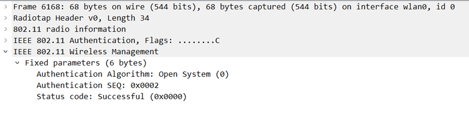
These frames should always work and once these frames have completed, the STA is in state 2.
STATE 3: Authenticated and Associated
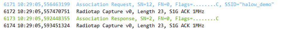
To get to state 3 we need to go through the association process by sending/receiving the Association Request and Association Response frames.
The S1G STA will send a Association Request to the S1G AP and announce its capabilities, this association request is again very similar to a regular association.
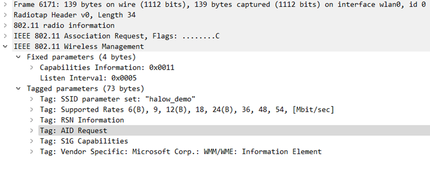
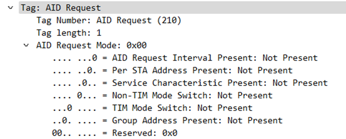
In the Association Request we see the AID Request Information Element (210), this AID Request element will inform the S1G AP about the characteristics of the S1G STA. If we dig into this IE we see the following content
In the 802.11-2020 standard this Information Element is broken down into the frame format below
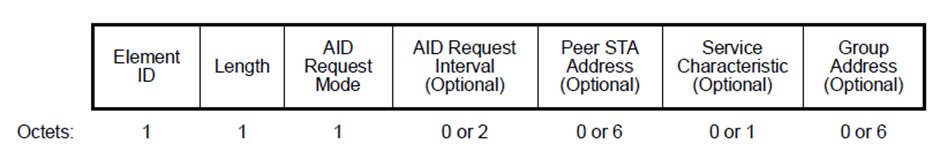
- Element ID and length are both 1 byte long
- AID Request mode can be split into more subfields, based on the content of the AID Request IE. If the optional fields like AID Request Interval, Peer STA Address, Service Characteristic and Group Address contain a value in that case the AID Request Mode field will contain values. In the current Association Request we captured this is all 0 or not present in the PCAP.
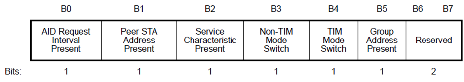
- AID Request Interval field will show the listen interval in units of beacon interval or short beacon interval to the S1G AP when the STA will wake up in TIM mode, in non-TIM mode is required to transmit a PS-Poll or a group listen interval when the non-AP STA wakes up to receive the S1G Beacon that shows when group address buffered frames for the group MAC address are present.
- Peer STA Address field indicates the MAC address of the peer STA for STA-to-STA communication
- Service Characteristic field indicates the information provided by the non-AP STA so that the AP can assign a particular AID to the STA based on the service characteristic when the STA associates or requests AID switch. The Service Characteristic field can be subdivided in more subfields
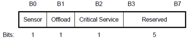
- Sensor subfield is set to 1 if the S1G STA is doing sensor services like temperature or other metering services. Otherwise it is 0
- Offload subfield show the STA is capable of offloading traffic, in that case it is set to 1 otherwise it is 0.
- Critical Service subfield is set to 1 when it provides critical services for health care, home, industrial, alarm monitoring or emergency services. AT the moment we looking for a S1G sensor that can provide these services to test more on its capabilities.
- Group Address field shows the group MAC Address of the requesting STA. If the group Address field is present in the AID Request element, the AID Request is put in an AID Switch Request frame to request a group AID.
The Association Request will be Acknowledged by a NDP CMAC ACK frame on 1MHz.
The S1G AP will sent the Association Response to the STA, below is how our Association Response looks like in Wireshark.
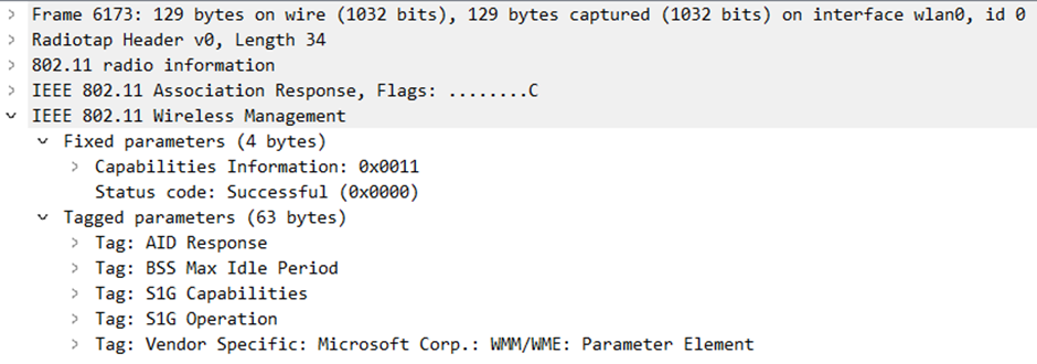
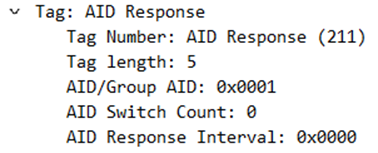
As discussed in the Association Request frame we see an AID Response as an Information Element (211). The AID Response shows shows the AID/Group AID field, switch count and response interval.
Below is the AID Response frame format according to the 802.11-2020 standard
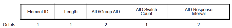
- Element ID and length is both 1 byte
- AID/Group AID field shows the AID that is assigned to the S1G STA, if the S1G AP changes the AID of the STA this field will contain the changed AID for the STA otherwise it will contain the current AID. It can also contain the Group AID that is assigned to a group address MAC.
- AID Switch count field shows the countdown value in units of (short) beacon interval that the AP sets for the STA to switch to a new AID. The AID Switch count field is set to 0 in an AID Response element that is carried in an Association Response frame.
- AID Response Interval field will show the listen interval in units of beacon interval or short beacon interval to the S1G AP when the STA should wake up in TIM mode, in non-TIM mode is required to transmit a PS-Poll or a group listen interval when the non-AP STA wakes up to receive the S1G Beacon that shows when group address buffered frames for the group MAC address are present.
Another Information Element we find in the Association Response is the BSS Max Idle Period. This information element is use to show the STA how long it can be idle before it can be disassociated by the AP. The STA is considered idle if the AP has not received a data, PS-Poll or management frame. BSS Max Idle Period provides improved STA power saving and AP resource management.
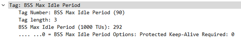
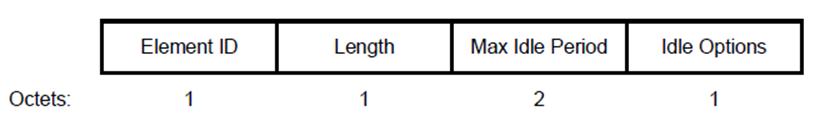
- BSS Max Idle Period is specified in units of 1000 TUs.
- Idle Options can require protected keep-alive frames, the AP may disassociate the STA if no protected frames have been received for the Idle period specified. If Protected Keep-Alive Required is set to 0 then the AP allows unprotected and protected keep-alive frames. If set to 1 only protected keep-alive frames are allowed.
After the association response a NDP CMAC ACK is received to confirm good reception. Once association request and association response process is done we completed state 2 and the STA/AP can move to state 3.
STATE 4: Authenticated and Associated, Controller port unblocked
To complete my authentication I need to go through the 4-way handshake, in this demo I have configured WPA2 on the S1G AP. With more equipment I could also capture WPA3 authentication to provide more security on the S1G SSID.
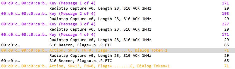
The 4-way handshake is completely similar to what we can see in a regular authentication on 2.4 and 5GHz. Once the 4-way handshake is completed the controller port is unblocked and we can request an IP address. Immediately after the controller port is unblocked S1G AP requesting blockACK request to the S1G STA in the Action frame.
I hope you liked this read about how a S1G client is authenticating and associating to a S1G AP
For now many thanks, if you see typo or have remarks please let me know and I will update